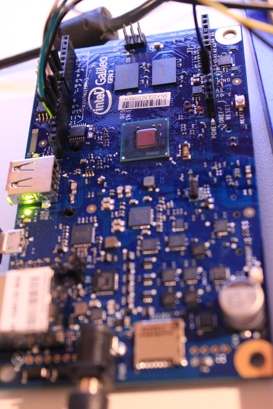
 Guys from Newark element14 have sent me a nice dev board - Intel Galileo Gen2. I was curious because before, Microsoft declared that Windows 10 IoT Core will run on this board. I planned to run my previous benchmark on this board to see if it can beat Raspberry PI 2. Unfortunately, with the latest release they removed this board from the compatibility list :(
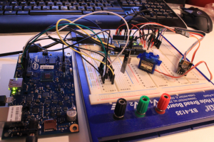
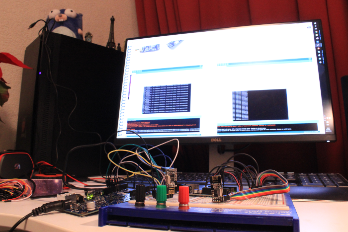
But this is not a big problem because I have some plans about home automation and I can use this board in it. I have couple nRF24L01 modules in my desk, so I've decided to test how good this module will work with Galileo board. To test wireless connection I need a second device, and I have one! Arduino Uno :) I've connected one nRF24L01 to the Galileo board and one to Arduino. Galileo has worked as transmitter and Arduino as a receiver. Now, I will describe how I did that.
Setup
- Download the Arduino Software
- Open Arduino IDE
- Go to Tools -> Board -> Boards Manager and install the Intel i586 core
- Connect Intel Galileo to power supply
- Connect it to USB
- Open example: File -> Examples -> 1.Basics -> Blink.
- Select board: Tools -> Boards -> Intel Galileo Gen2
- Select port: Tools -> Port -> COM# (where # is number, usually 3)
- Press Upload button
- You should see blinking LED
Install nRF24L01 library
Now we need some library to work with nRF24L01. Here you can find a lot of them, I will use RF24.
- Download library
- In Arduino IDE go to Sketch -> Include Library -> Add .Zip Library...
- Select downloaded archive
- Done!
Send data
Let's send some data to test if this library is working well. We will send current time to the other board and will receive a response with the same data. Also we will calculate a time between send and receive operations.
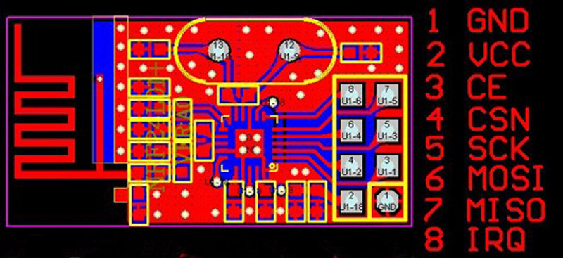
But we first need to connect nRF24L01 to our boards. Here is pinout from nRF24L01:
and this is how you should connect it:
PIN	NRF24L01	Intel Galileo Gen2
1	GND	        GND
2	VCC	        3.3V
3	CE	        digIO 7
4	CSN	        digIO 8
5	SCK	        digIO 13
6	MOSI	    digIO 11
7	MISO	    digIO 12
8	IRQ	        -
You should use the same for Arduino board.
Now open new sketch and past this code:
/*
* Getting Started example sketch for nRF24L01+ radios
* This is a very basic example of how to send data from one node to another
* Updated: Dec 2014 by TMRh20
*/
#include <SPI.h>
#include "RF24.h"
/****************** User Config ***************************/
/***      Set this radio as radio number 0 or 1         ***/
bool radioNumber = 0;
/* Hardware configuration: Set up nRF24L01 radio on SPI bus plus pins 7 & 8 */
RF24 radio(7,8);
/**********************************************************/
byte addresses[][6] = {"1Node","2Node"};
// Used to control whether this node is sending or receiving
bool role = 0;
void setup() {
  Serial.begin(115200);
  Serial.println(F("RF24/examples/GettingStarted"));
  Serial.println(F("*** PRESS 'T' to begin transmitting to the other node"));

  radio.begin();
  // Set the PA Level low to prevent power supply related issues since this is a
 // getting_started sketch, and the likelihood of close proximity of the devices. RF24_PA_MAX is default.
  radio.setPALevel(RF24_PA_LOW);

  // Open a writing and reading pipe on each radio, with opposite addresses
  if(radioNumber){
    radio.openWritingPipe(addresses[1]);
    radio.openReadingPipe(1,addresses[0]);
  }else{
    radio.openWritingPipe(addresses[0]);
    radio.openReadingPipe(1,addresses[1]);
  }

  // Start the radio listening for data
  radio.startListening();
}
void loop() {


/****************** Ping Out Role ***************************/
if (role == 1)  {

    radio.stopListening();                                    // First, stop listening so we can talk.


    Serial.println(F("Now sending"));
    unsigned long time = micros();                             // Take the time, and send it.  This will block until complete
     if (!radio.write( &time, sizeof(unsigned long) )){
       Serial.println(F("failed"));
     }

    radio.startListening();                                    // Now, continue listening

    unsigned long started_waiting_at = micros();               // Set up a timeout period, get the current microseconds
    boolean timeout = false;                                   // Set up a variable to indicate if a response was received or not

    while ( ! radio.available() ){                             // While nothing is received
      if (micros() - started_waiting_at > 200000 ){            // If waited longer than 200ms, indicate timeout and exit while loop
          timeout = true;
          break;
      }
    }

    if ( timeout ){                                             // Describe the results
        Serial.println(F("Failed, response timed out."));
    }else{
        unsigned long got_time;                                 // Grab the response, compare, and send to debugging spew
        radio.read( &got_time, sizeof(unsigned long) );
        unsigned long time = micros();

        // Spew it
        Serial.print(F("Sent "));
        Serial.print(time);
        Serial.print(F(", Got response "));
        Serial.print(got_time);
        Serial.print(F(", Round-trip delay "));
        Serial.print(time-got_time);
        Serial.println(F(" microseconds"));
    }
    // Try again 1s later
    delay(1000);
  }
/****************** Pong Back Role ***************************/
  if ( role == 0 )
  {
    unsigned long got_time;

    if( radio.available()){
                                                                    // Variable for the received timestamp
      while (radio.available()) {                                   // While there is data ready
        radio.read( &got_time, sizeof(unsigned long) );             // Get the payload
      }

      radio.stopListening();                                        // First, stop listening so we can talk
      radio.write( &got_time, sizeof(unsigned long) );              // Send the final one back.
      radio.startListening();                                       // Now, resume listening so we catch the next packets.
      Serial.print(F("Sent response "));
      Serial.println(got_time);
   }
 }
/****************** Change Roles via Serial Commands ***************************/
  if ( Serial.available() )
  {
    char c = toupper(Serial.read());
    if ( c == 'T' && role == 0 ){
      Serial.println(F("*** CHANGING TO TRANSMIT ROLE -- PRESS 'R' TO SWITCH BACK"));
      role = 1;                  // Become the primary transmitter (ping out)

   }else
    if ( c == 'R' && role == 1 ){
      Serial.println(F("*** CHANGING TO RECEIVE ROLE -- PRESS 'T' TO SWITCH BACK"));
       role = 0;                // Become the primary receiver (pong back)
       radio.startListening();

    }
  }
} // Loop
This is default example from the RF24 library. We will run this code on both boards, the only difference is line number 10:
bool radioNumber = 0;you should change it to:
bool radioNumber = 1;before uploading to Arduino, so Intel Galileo will have radioNumber set to 0 and Arduino to 1.
- Upload this sketch to both Arduino and Galileo.
- Keep both boards connected via USB
- Open putty
- Connect one instance of putty to Serial COM3 (Galileo port) with 115200 baud
- Other one to COM4 with the same speed
- In first terminal press T
- You should see messages about sending and receiving data.
- If not, check your circuit and code (do not forget about radioNumber).
Here is more photos from my evening:
In the next article, I will describe linux side of the Intel Galileo Gen2 board.


